[8M] Gravity race car
For the third-year group project, our group of 4 was tasked with building the fastest gravity powered racecar (racing down a slope). We designed the car and the manufacturing process in 9 months. This page is a summary of the project.
Design - shell and chassis
Introduction
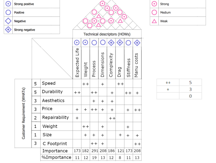
The design of the chassis aims at maximizing ruggedness and aerodynamics, while the mold emphasizes simplicity. Utilizing background knowledge, FEA simulations, and physical testing, a product was created to meet these specified goals. This package outlines the technical justifications for both design requirements and design choices.
Part Design
Geometry
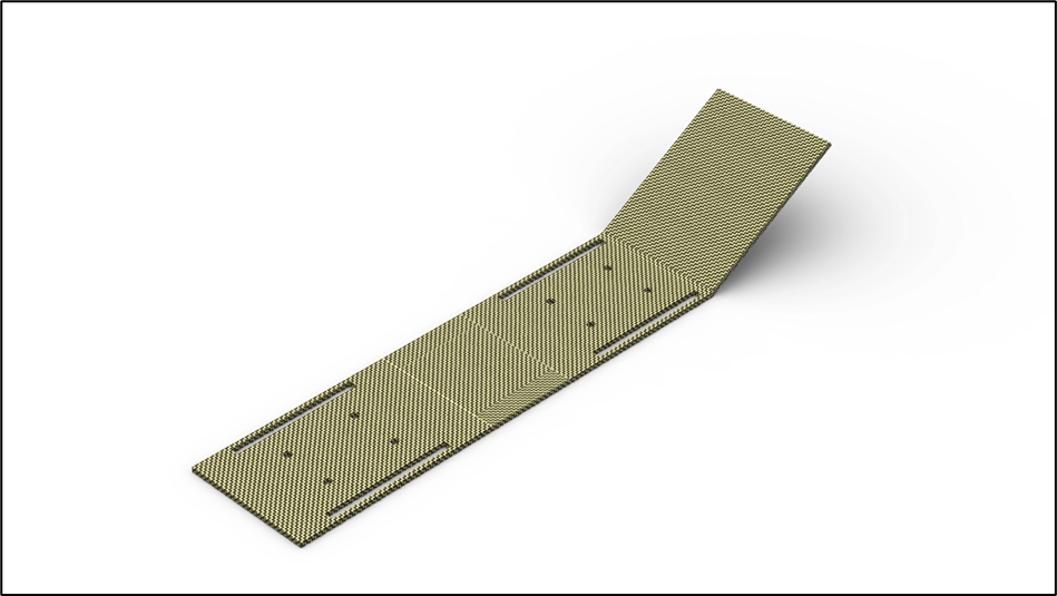
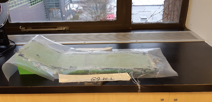
Akin to the thermoformed body, the composite chassis prioritizes aerodynamics and ease of manufacturability.
The rear angling of the chassis allows for the car to take on a tear-dropped profile. This significantly reduces the turbulent flow at the rear of the car and minimizes the induced drag force. Keeping in line with being simple to manufacture, no post-processing procedures (apart from finishing the edges) are required on the angled part.
Tolerances
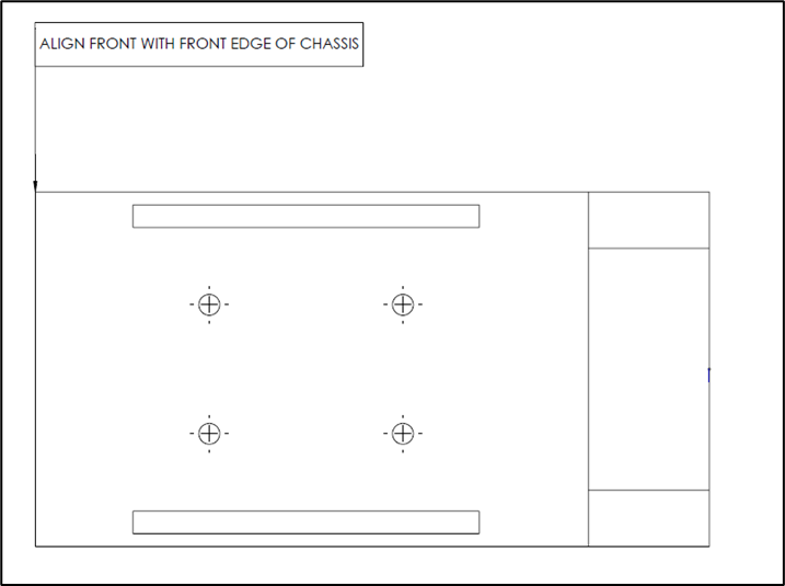
The tolerances were designed to maximize efficiency. Given that the post-processing would be done entirely by hand, the dimensions of the wheel clearance slots were designed with ±5mm in mind. Furthermore, the utilization of hex head bolts allowed for the holes to be oversized. With a larger head surface area, the bolts would be able to clamp properly when set into a larger hole. In this case, the acceptable deviation was +0.125in and -0.0in.
The only tolerances that required high precision were the alignment of the features. For example, if the bolt holes were significantly off-center, the axle would end up slanted with one wheel further forward than the other. This would cause an imbalance in the car and hamper performance.
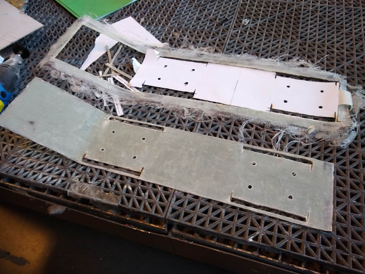
Assembly
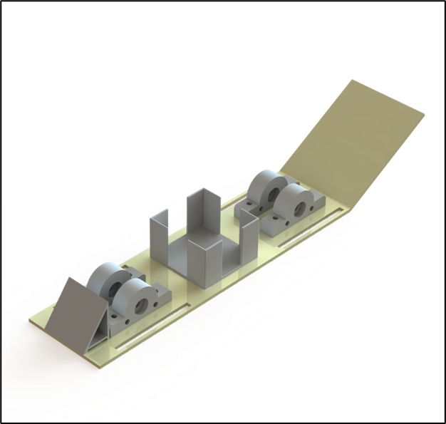
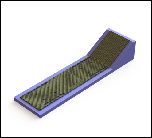
Tooling Design
Geometry
Material Selection
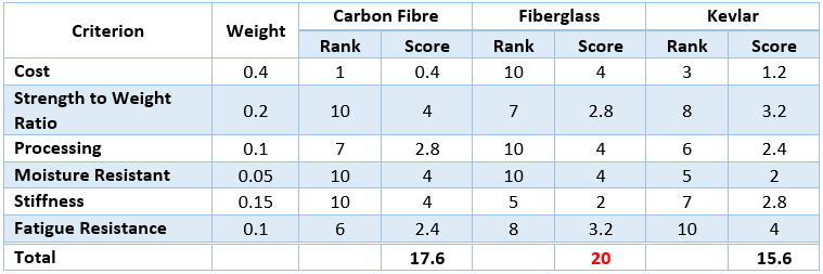
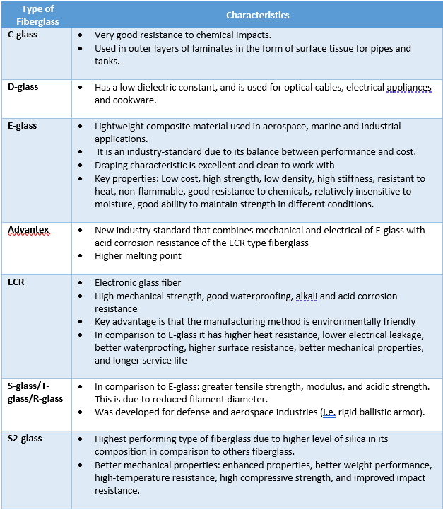
Decision: E-glass
Process selection
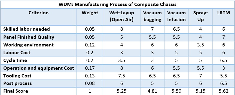
Decision: Light resin transform molding (LRTM)
Manufacturing Method Analysis
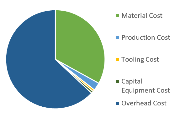
Cost Estimate
All costs listed below are in CAD.
Material Cost
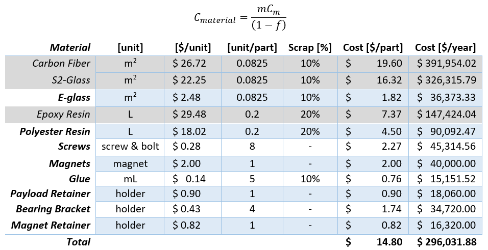
Total estimated cost for a year was ~ $ 687,000. Therefore, by increasing the number of stations to 6 each, costs were reduced by ~ 29%.
Engineering Science Analysis
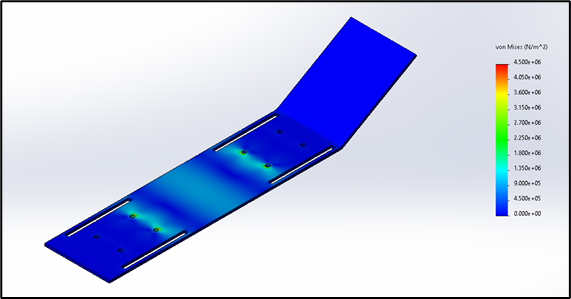
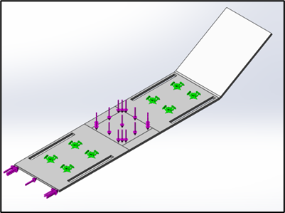
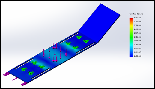
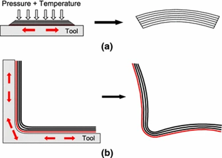
Bending

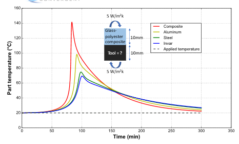
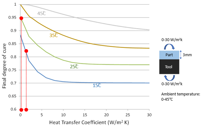
Part and Tooling Thermal Analysis
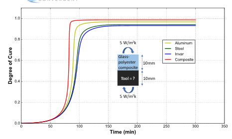
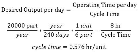
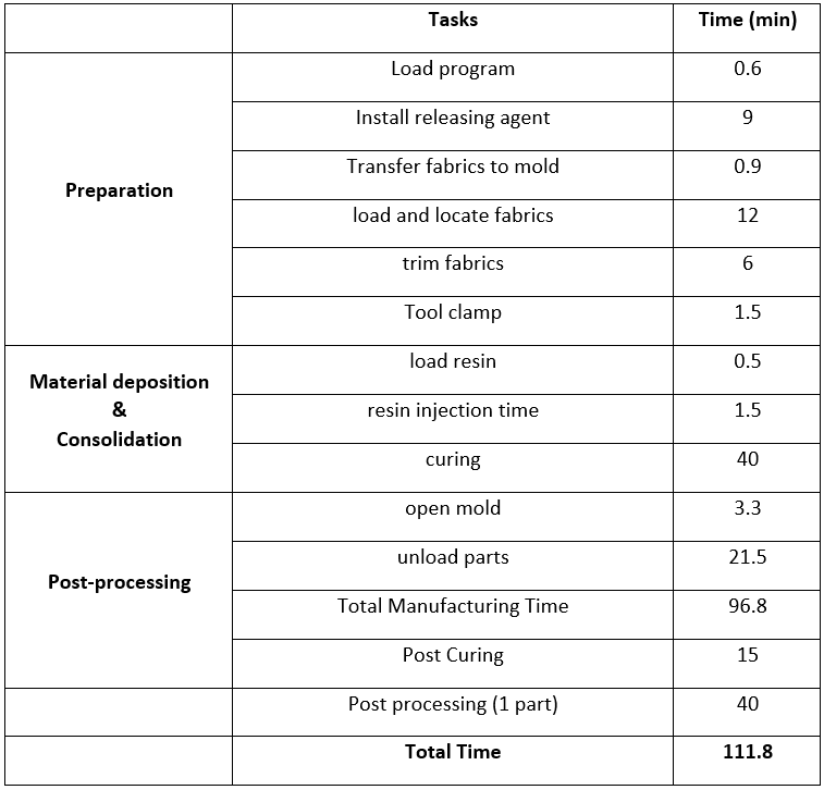
Cycle time estimation
Experimentation and Testing
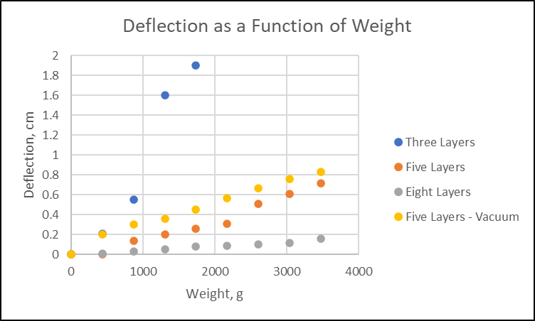
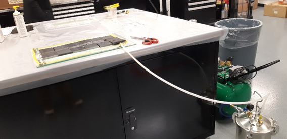
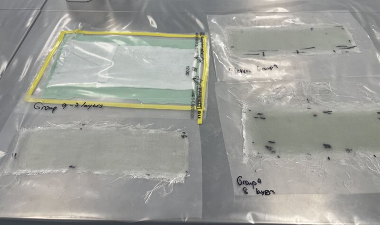
Vacuum Assisted Process vs. Open-air process

Post Processing time Test
External Research
Shape of Chassis
Chassis was shaped as flat as possible, and avoiding angles approaching 90 degrees. [22]
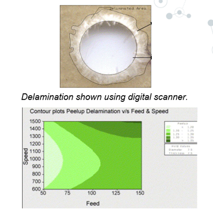
Post processing - drilling
Drilling is a viable post processing method for the holes, if done at high cutting speed and low feed.[23]
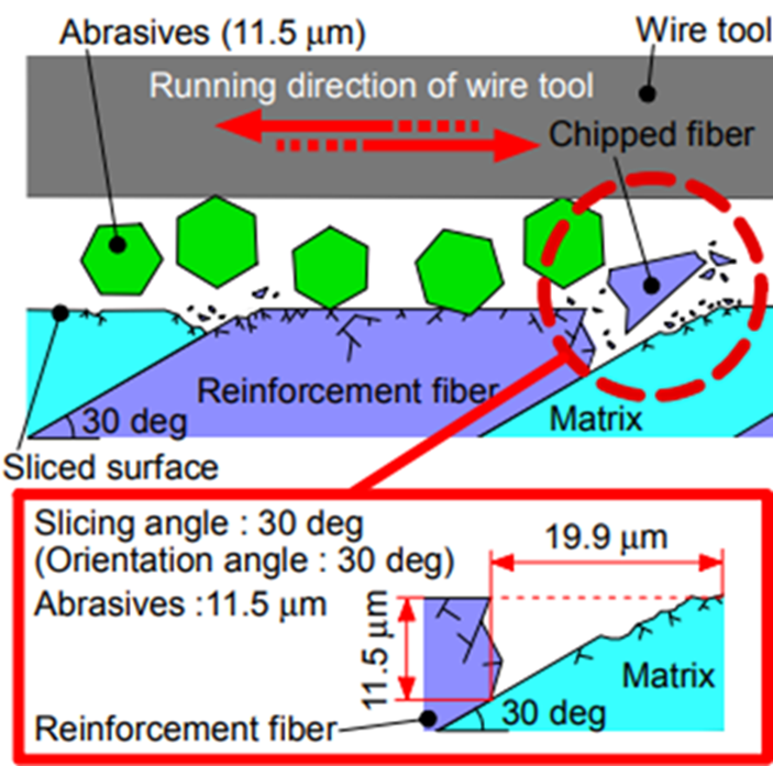
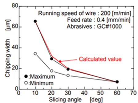
Post processing – Saw Cutting
Using a saw is a viable post processing method for smooth edges, with minimal chipping - if done at appropriate slicing angles.[23]
References
[1] 15 Different Types of Fiberglass. (n.d.). Stratosphere. Retrieved February, 12, 2022 from https://www.homestratosphere.com/types-of-fiberglass/#1A-GlassFiber
[2] Arlen Hoebergen, J. Anders Holmberg, Vacuum Infusion, Composites, Vol 21, ASM Handbook, Edited By Daniel B. Miracle, Steven L. Donaldson, ASM International, 2001, p 501–515, Retrieved February 27, 2022, from https://doi.org/10.31399/asm.hb.v21.a0003414
[3] Back to Basics: Carbon Fiber vs Fiberglass. (n.d.). Composite Envisions. Retrieved February, 12, 2022 from https://compositeenvisions.com/back-to-basics-carbon-fiber-vs-fiberglass-vs-kevlararamid/
[4] deMerchant, Christene. (n.d.). Comparison of Carbon Fiber, Kevlar (Aramid), and E Glass used on Composites for Boatbuilding. Retrieved February 12, 2022 from https://www.christinedemerchant.com/carbon-kevlar-glass-comparison.html
[5] Effect of equipment in a thermal management system. (n.d.). Retrieved February 27, 2022, from https://compositeskn.org/KPC/A110
[6] Effect of tooling in a thermal management system - A142. (n.d.). Retrieved February 27, 2022, from https://compositeskn.org/KPC/A142#Tooling_configuration
[7] Ensuring tooling choice meets part quality metrics. (2021, April 28). Retrieved February 22, 2022, from https://compositeskn.org/KPC/P128
[8] Finn Roger Andresen, Open Molding: Hand Lay-Up and Spray-Up, Composites, Vol 21, ASM Handbook, Edited By Daniel B. Miracle, Steven L. Donaldson, ASM International, 2001, p 450–456, Retrieved February 27, 2022, from https://doi.org/10.31399/asm.hb.v21.a0003406
[9] How to Cut Fiberglass – 6 Tips for Cutting Fiberglass in the Best Way (2021, February 24). NC Cutting Tools. Retrieved March 1, 2022 https://www.nccuttingtools.com/how-to-cut-fiberglass.html
[10] Injection Molding for High-density Polyethylene (HDPE) Parts. (n.d.) Protolabs. Retrieved February 25, 2022 from https://www.protolabs.com/services/injection-molding/hdpe/.
[11] Isoldi, L., Oliveira, C., Rocha, L., Souza, J., & Amico, S. (2012, June 01). Three-dimensional numerical modeling of RTM and LRTM Processes. Retrieved February 22, 2022, from https://www.scielo.br/j/jbsmse/a/dmv6NqGsZDQZgLM4htSntxG/?lang=en#
[12] Johnson, Todd. (2021, February 16). Thermoplastic vs. Thermoset Resins. Retrieved February 18, 2022 from https://www.thoughtco.com/thermoplastic-vs-thermoset-resins-820405
[13] Light resin transfer molding. (n.d.). Retrieved February 27, 2022, from https://www.compositesworld.com/kc/closed-molding/processes/light-rtm
[14] Melito, Steve. (2021, July 29). The Ten Most Common Plastic Injection Molding Materials. Retrieved February 25, 2022 from https://www.fictiv.com/articles/the-ten-most-common-plastic-injection-molding-materials
[15] New Production Processes to be implemented in the project 01/07/2021. (n.d.). Retrieved February 27, 2022, from https://www.readkong.com/page/new-production-processes-to-be-implemented-in-the-project-3758224
[16] Pros & Cons: Composites Manufacturing Methods │rock west composites. (n.d.). Retrieved February 27, 2022, from https://www.rockwestcomposites.com/pros-cons-composites-manufacturing-methods
[17] Revisiting the fundamentals of Light Resin Transfer Molding (LRTM). (n.d.). Retrieved February 27, 2022, from https://www.compositesworld.com/articles/revisiting-the-fundamentals-of-light-resin-transfer-molding-lrtm
[18] Safety in Workplace With Fiberglass Dust (2020, October 26). Chron. Retrieved March 1, 2022 from https://work.chron.com/safety-workplace-fiberglass-dust-12877.html
[19] The Fundamentals of Fiberglass. (n.d.). Fibreglast. Retrieved February 12, 2022, from https://www.fibreglast.com/product/the-fundamentals-of-fiberglass/Learning_Center
[20] 2014 design training expo – American Composites Manufacturing Association, Retrieved March 1, 2022 from https://www.fdot.gov/docs/default-source/design/training/designexpo/2014/presentations/GevinMcDaniel-FRP-Composites.pdf
[21] Ashok Kumar, U., Mehtab Alam, S., & Laxminarayana, P. (2020). Influence of abrasive water jet cutting on glass fibre reinforced polymer (GFRP) composites. Materials Today: Proceedings, 27, 1651–1654. https://doi.org/10.1016/j.matpr.2020.03.554
[22] Baran, I., Cinar, K., Ersoy, N., Akkerman, R., & Hattel, J. H. (2016). A Review on the Mechanical Modeling of Composite Manufacturing Processes. Archives of Computational Methods in Engineering, 24(2), 365–395. https://doi.org/10.1007/s11831-016-9167-2
[23] Mohan, N., Kulkarni, S., & Ramachandra, A. (2007). Delamination analysis in drilling process of glass fiber reinforced plastic (GFRP) composite materials. Journal of Materials Processing Technology, 186(1–3), 265–271. https://doi.org/10.1016/j.jmatprotec.2006.12.043
[24] Sakamoto, S., Yamaguchi, M., Kondo, Y., Yamaguchi, K., & Nomura, A. J. (2014). Surface Characteristics Produced by Multi-Wire Sawing of GFRP. Key Engineering Materials, 625, 597–602. https://doi.org/10.4028/www.scientific.net/kem.625.597