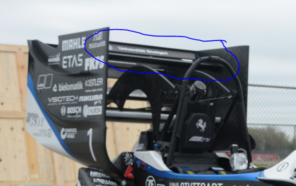
[3M] Race car rear tandem wings
Explored the possibility of 2 rear-mounted tier 3 wings similar to those shown in Fig.1
Litereture Review
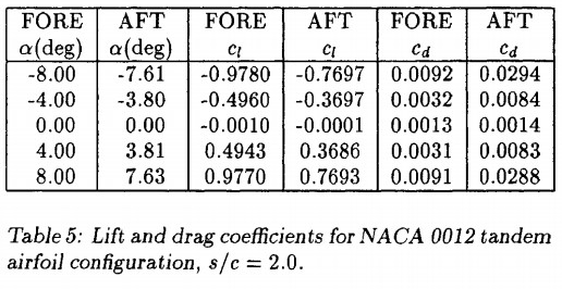
Fanjoy, D. and Dorney, D., "Numerical Simulations of Tandem-Airfoil Aerodynamics," SAE Technical Paper 961295, 1996,
The tandem geometry was modeled using two NACA 0012 airfoils. The inlet Mach number was set at M = 0.20 and the Reynolds was specified to be 6x10^6.

In addition, the downwash from the fore airfoil causes the aft airfoil to operate at a lower local angle of attack (see Table 2), which is desirable from the standpoint that the fore airfoil will stall first.

The fore airfoil will have a greater lift-to-drag ratio than the aft airfoil
The lift on the fore airfoil increases above that for an isolated airfoil and the drag is substantially reduced.
Decreasing the stagger distance results in:
1) increased lift and reduced drag on the fore airfoil, and
2) reduced lift and increased drag on the aft airfoil.
Thus, there is an optimum stagger distance associated with maximum airfoil performance. Future work will focus on varying the vertical distance (or gap) between the two airfoils. In addition, the effects of periodic unsteadiness will be investigated.
Conclusion: Lift from the fore airfoil seems to compensate for the reduction in lift from the aft airfoil. Total drag on the system seems to reduce. Tandem wings seem to be worth pursuing.
Variables:
Stagger distance
Height difference
Angle of attacks (independent)
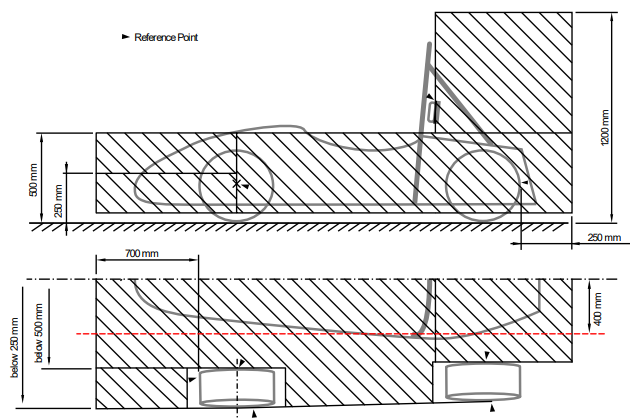
Requirement: Wings must be attached to endplate, thus maximum stagger distance and maximum height difference is determined by dimensions allowed in rulebook.
T.7.3 , T.7.4, T.7.5
T.7.4.1 In plan view, any part of any Aerodynamic Device must be:
a. No more than 250 mm rearward of the rear of the rear tires
b. No further forward than a vertical plane through the rearmost portion of the front face of the driver head restraint support, excluding any padding, set (if adjustable) in its fully rearward position (excluding undertrays).
T.7.4.2 In side elevation, any part of an Aerodynamic Device must be no higher than 1.2 meters above the ground when measured without a driver in the vehicle

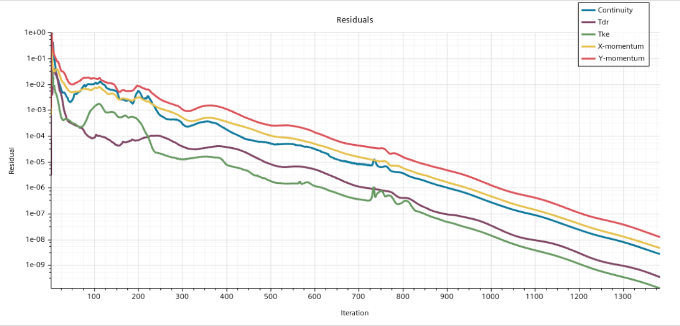
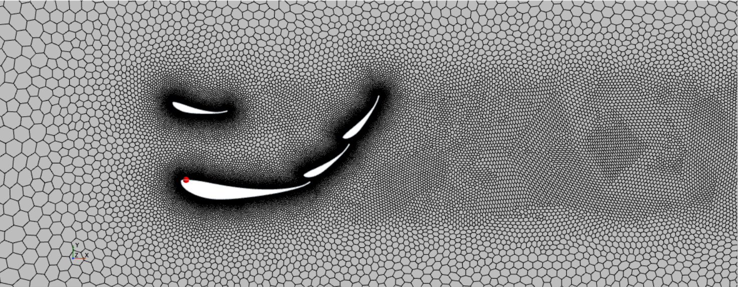
Mesh seems workable for old geometry, but not for the new geometry. CFD studies follow.
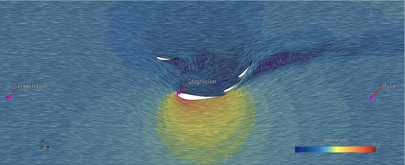
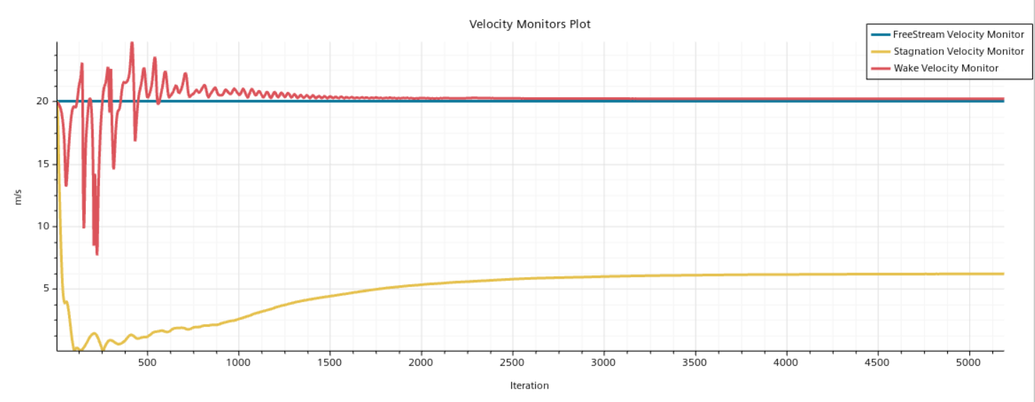
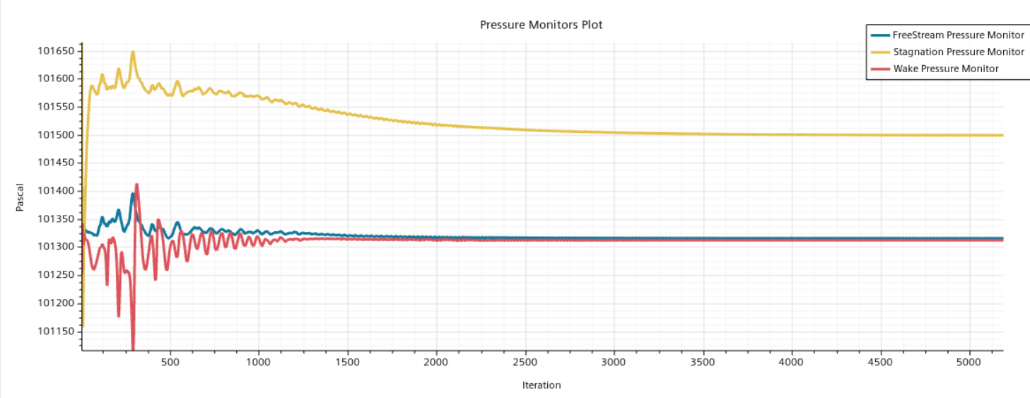
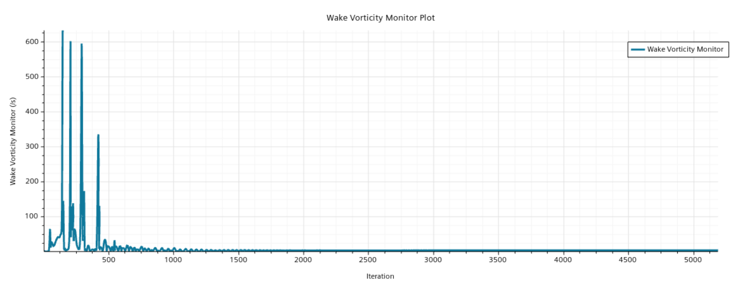
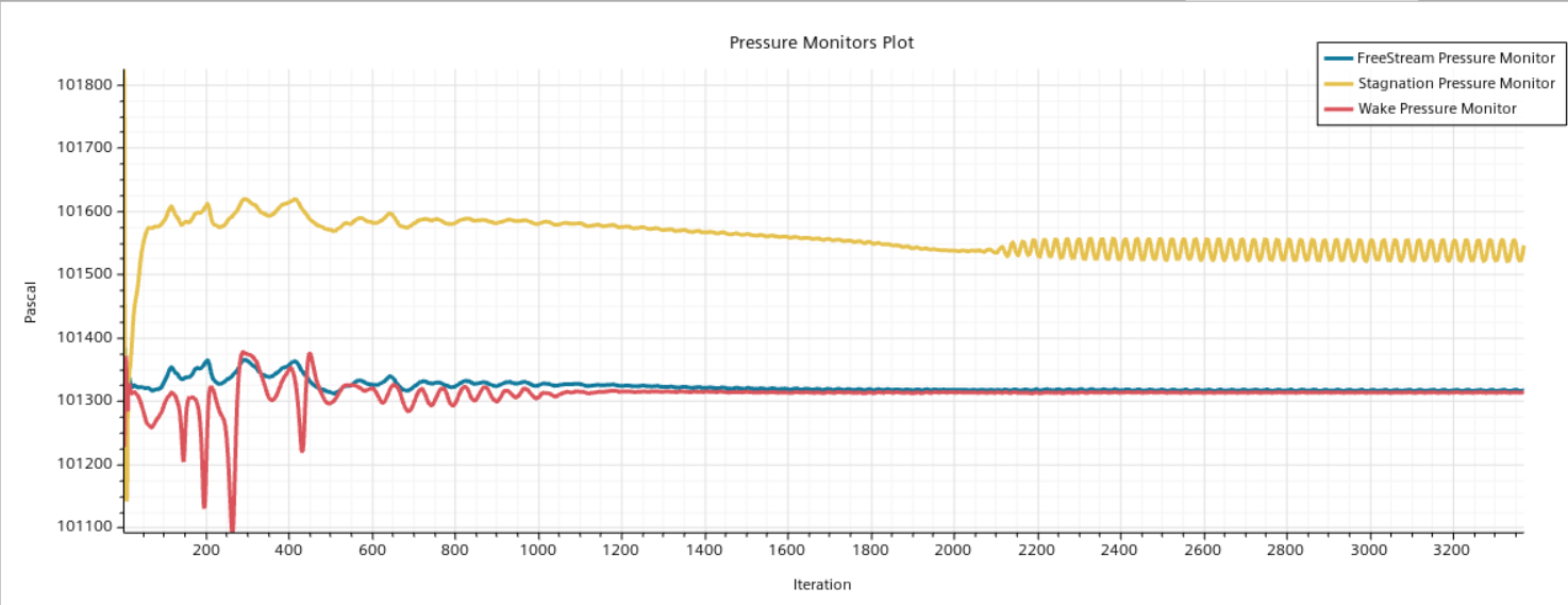
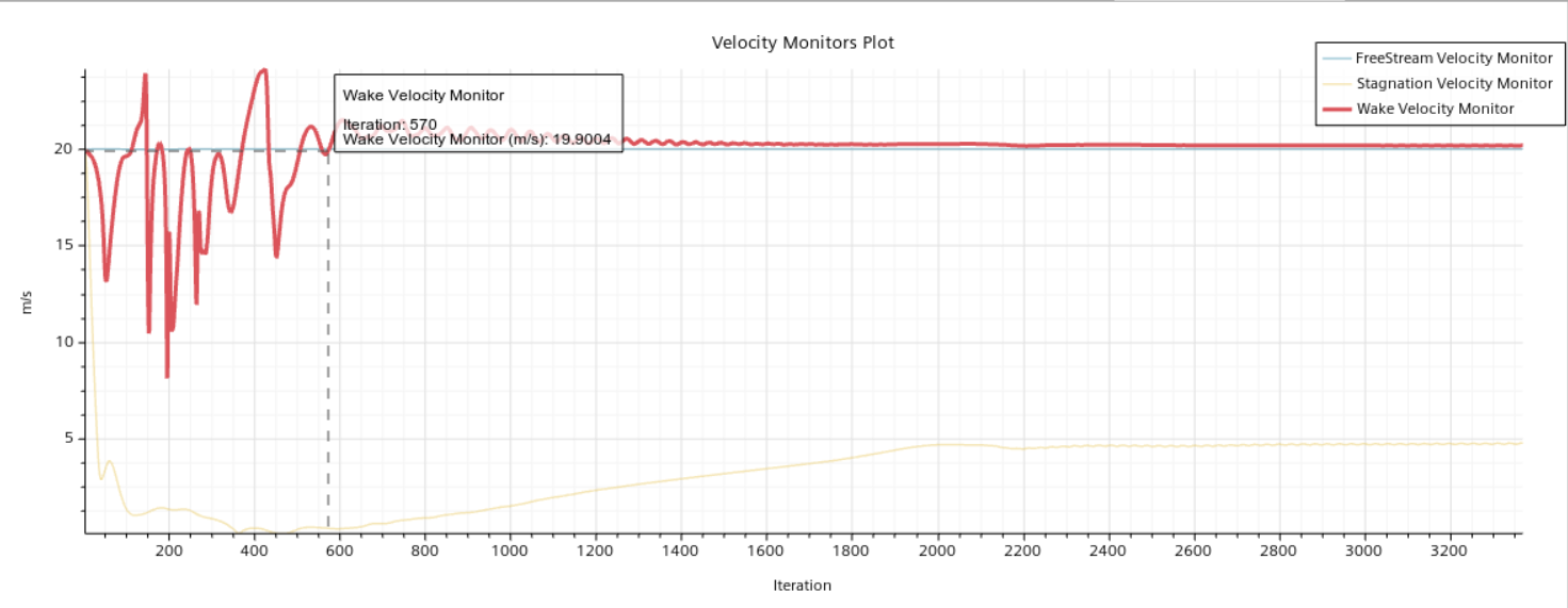
We set some point monitors
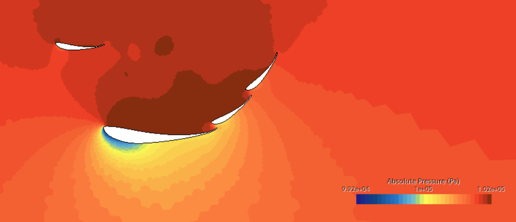
This simulation is first run without the tandem wing.
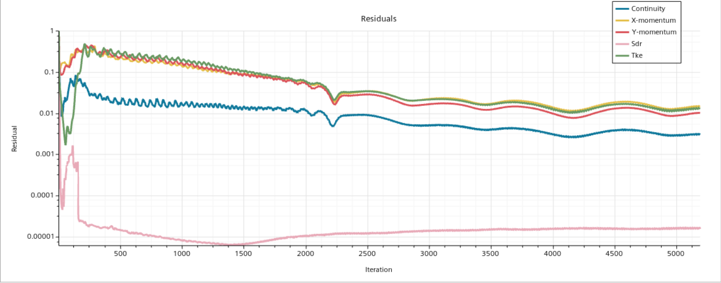
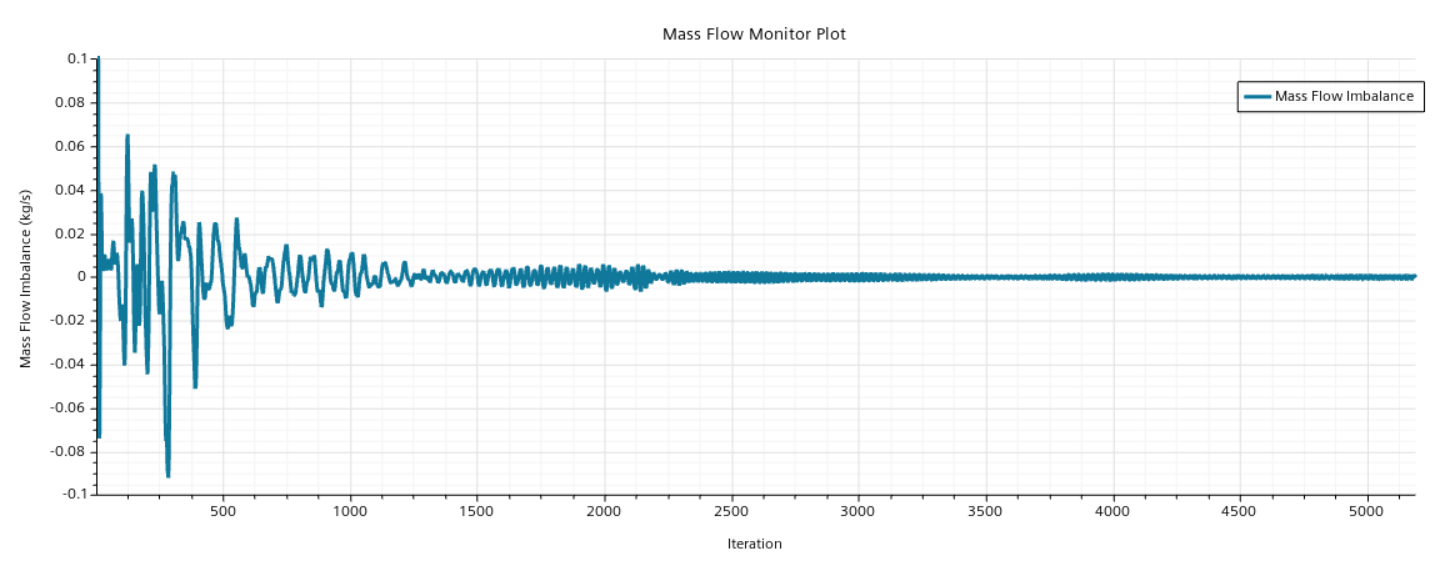
Maximum of 'Mass Flow Imbalance'
Computed Value: 1.197582e-03 kg/s
Location (Iteration): 4204
Sample Range (Iterations): [4201 .. 4500]
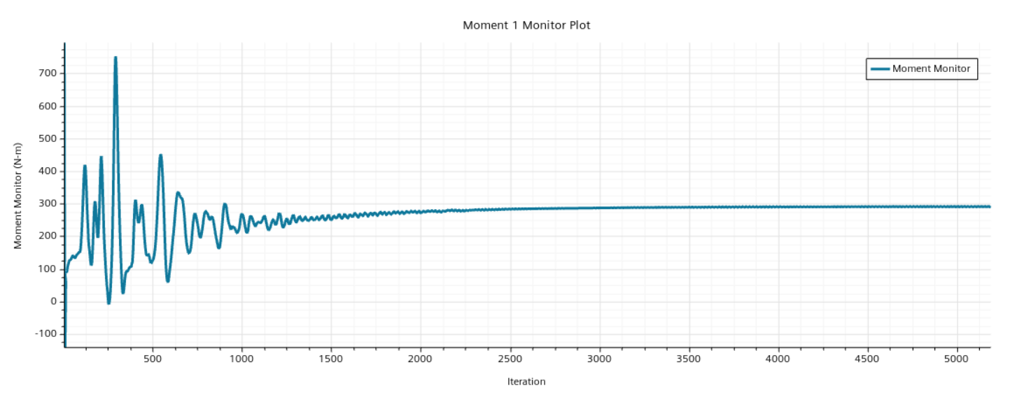
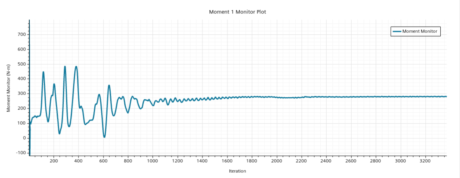
Mean of 'Moment Imbalance Amplitude Monitor'
Computed Value: 1.387479e+00
Sample Range (Iterations): [4201 .. 4500]
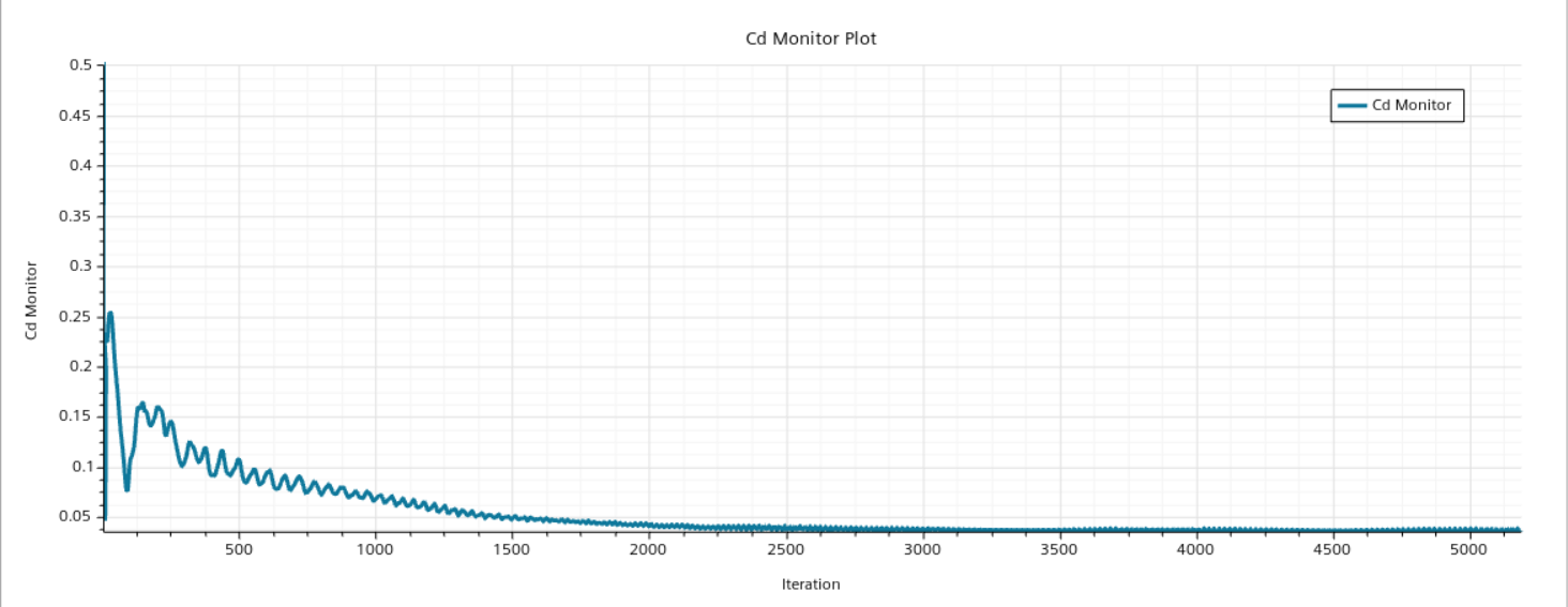
Mean of 'Cd Monitor'
Computed Value: 3.651193e-02
Sample Range (Iterations): [4201 .. 4500]
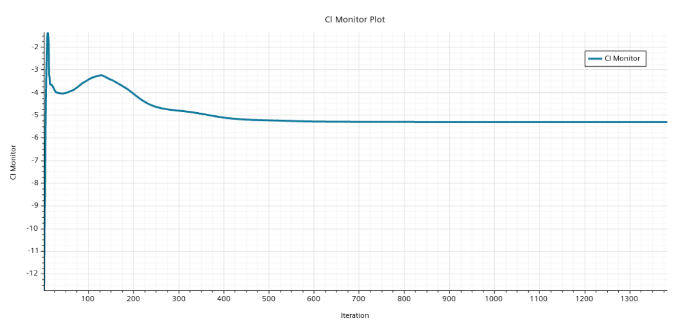
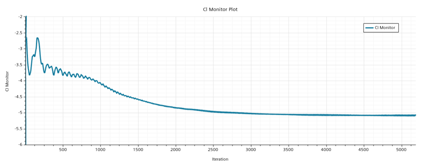
Mean of 'Cl Monitor'
Computed Value: -5.073615e+00
Sample Range (Iterations): [4201 .. 4500]
${MeanClReport}/${MeanCdReport} = -1.389577e+02
=-139.0
Mean of 'Downforce Monitor'
Computed Value: 5.542796e+02 N
Sample Range (Iterations): [4201 .. 4500]
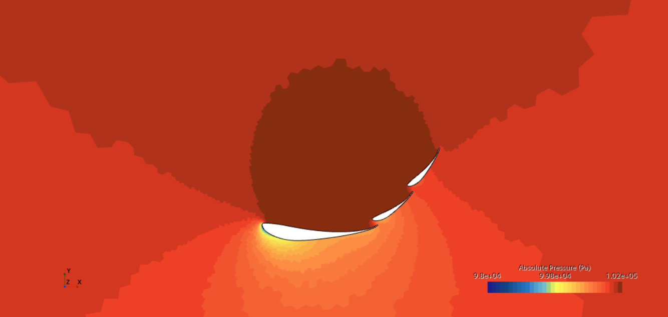
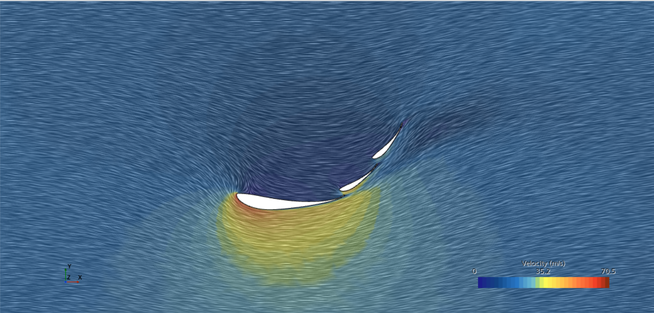
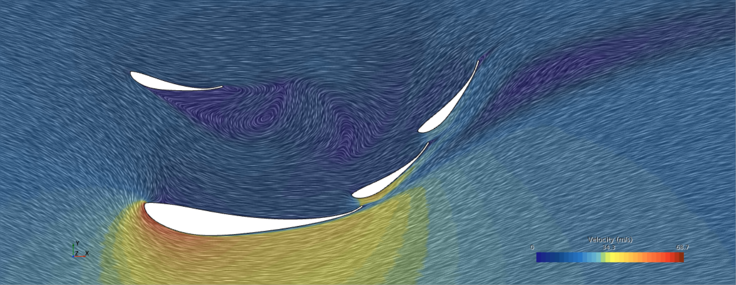
Adjusting tandem wing to rules based max-distance placement, and design study was conducted for 10 different AoAs. Important results are given below:
20 degrees AoA, [-0.02 height]
-28 AoA, [-0.02 height]
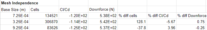
Mesh Independence Study
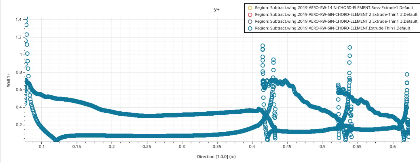
The precise definitions of the boundary layers for each element will be preserved through all simulations because it is not productive to wrongly predict near-wall behaviour.
Initial mesh - Base cell size of 7.25E-4 m
Volume Meshing Pipeline Completed: CPU Time: 66.40, Wall Time: 66.40, Memory: 103.80 MB Cells: 134521 Faces: 332758 Vertices: 200987


Mean of 'Cd Monitor'
Computed Value: 3.926207e-02
Sample Range (Iterations): [3069 .. 3368]
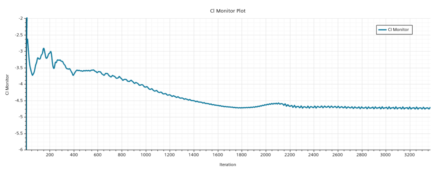
Mean of 'Cl Monitor'
Computed Value: -4.727662e+00
Sample Range (Iterations): [3069 .. 3368]
${MeanClReport}/${MeanCdReport} = -1.204130e+02
Mean of 'Downforce Monitor'
Computed Value: 5.383562e+02 N
Sample Range (Iterations): [3069 .. 3368]
These experiments were repeated for other mesh sizes and the results are shown below