[6M]Race car rear wing DRS
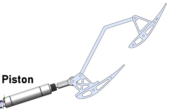
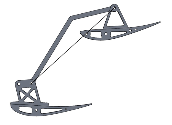
The Tier 2 and 3 elements on the rear wings are moved by a piston between a “low drag” (as pictured in Fig 1.3) and “high downforce” (as pictured in Fig 1.1) position. They are attached by a linkage, that has proved to allow too much compliance. The goal of this project is to reduce compliance. Straightening the linkage will increase linkage stiffness.
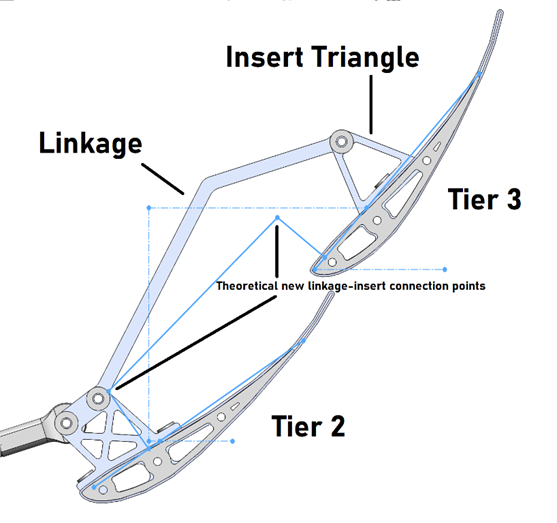
The first option considered to straighten the linkage is to move the linkage-insert connection point on the Tier 3 wing element forward to circumvent the problem of the linkage hitting the wing in the “low drag” position
Since the wings need to move through different arcs (the tier 3 element is at a sharper angle in the “high downforce” position) to reach the “low drag” position with the same piston force applied to both (albeit at different angles), the variables must be the moment arms (referred to as r1 and r2 in Fig 1.4) – between the point of rotation (middle hole of the tier 3 insert and first hole of the tier 2 insert) and the point of linkage-insert connection. First, A drawing of all the dimensions was created.
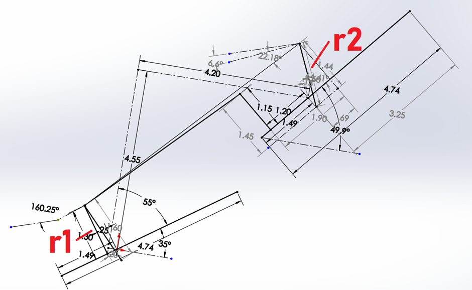
A spreadsheet was then created. Of the two variables (r1 and r2), r1 was kept constant since that was where the piston met the DRS system. The arcs that both the inserts follow must be the same, since they are connected by a linkage. Therefore, by varying r2 we can vary the angle that the tier 3 element moves by. We set the angle that it needs to move by, and we vary the position of the linkage-insert connection point on the tier 3 element while maintaining the required r2. We then find a suitable position for the linkage-insert connection point where the linkage will not interfere with the tier 3 element of the rear wing.
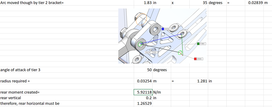
Thus, we arrive at a radius r2 (labelled radius required in Fig 1.5) that is required to impart a 50 degree change of angle into the tier 3 element of the rear wing when the tier 2 element is moved by 35 degrees. However, in the actual linkage, r1=r2 and the wing still behaves normally. Thus, our kinetic model must be flawed. Other methods like designing the system completely in CAD, depending on the Motion simulation to (through trial and error) get the correct motion ratio does not seem robust enough to implement. Thus this phase was abandoned.
Phase 2: Stiffening the linkage
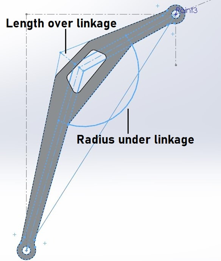
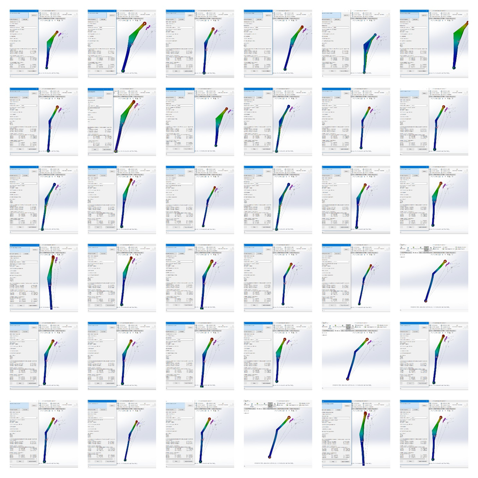
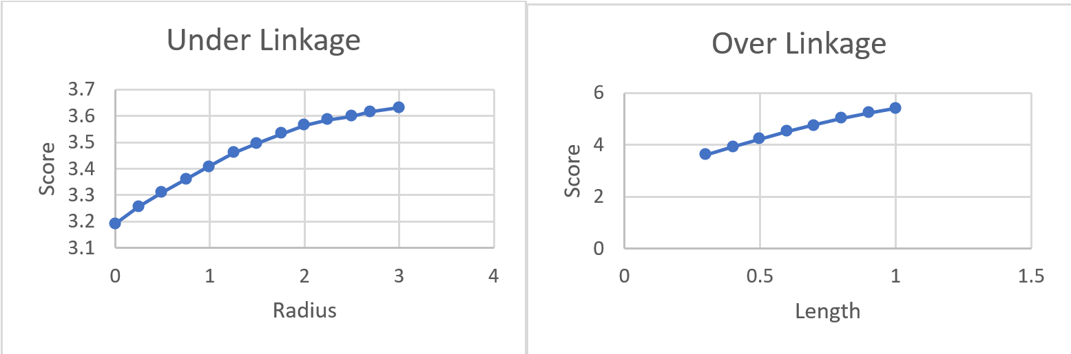
Since changing the insert seems infeasible, stiffening the linkage is the next best option. 1/8th inch 7075-T6 (SN) is the lightest available metal present. FEA studies are conducted extending the linkage upwards (with a length) and downwards (with a radius) as shown in Fig 2.1, and results are graphed as shown in Fig 2.2. Also in Fig 2.2 is the “score” which is calculated as the reciprocal of the displacement of that linkage shown in FEA multiplied by the weight of that linkage. This was done because lower displacement and lower weight is preferred in the final linkage.
Since all loading is in plane with the linkage, a topological study was then conducted to minimize weight.
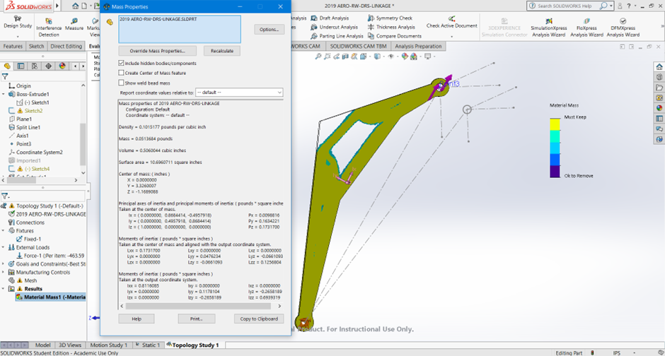
After this final shape was achieved, a fundamental oversight was realised. The shape that FEA testing started with (the old linkage) was a flawed starting point. Solid Mechanics dictates that sharp angles create points of stress, and thus a new linkage was conceptualised using only arcs starting with the connection points, of radii varying by the thickness of the previous linkage.
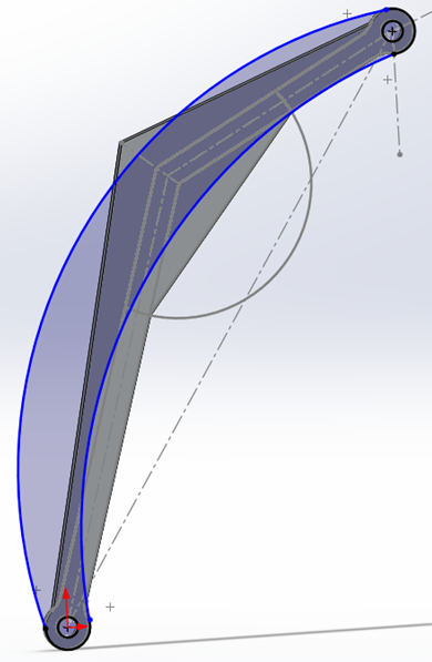
FEA was then conducted to test the possibility of such a linkage, and the results were the best so far, and weight reduction hadn’t been even been conducted yet.
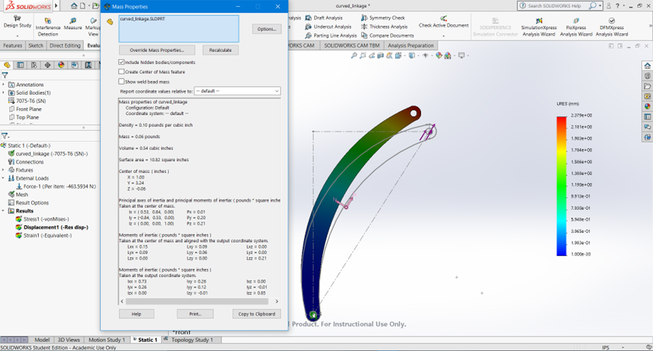
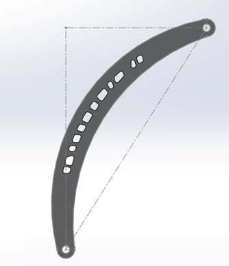
While this linkage had superior stiffness, its weight was higher than the weight of the linkage in Fig 1.5 by 0.007 pounds, so no iterations of the linkage were considered. The final linkage had the best weight-stiffness ratio of all the options considered.
FUBC Kaver Muthanna Ammatanda 2019-20